Symbols Used on Our DrawingsThese symbols are used on the Mechanical Models engine drawings as well as on many other drawings.
|
Symbols Used on Our DrawingsThese symbols are used on the Mechanical Models engine drawings as well as on many other drawings.
|


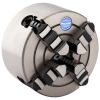 Lathe Chuck, 4-Jaw 4", Independent, Premium, Harlingen
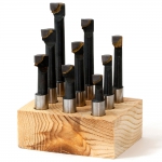 Boring Bar Set, 3/8" Shank, Carbide