Wiring Diagrams
These wiring diagrams show different applications of the controller boards we sell.
|
Diagram Number |
Application |
Controller |
|
2506 |
Wiring diagram for standard late model 7x12 mini lathe with red and yellow
emergency stop switch. |
FC250J/110V
LMS 1336 |
|
2507 |
Wiring diagram for late model mini lathe with red and yellow emergency stop
switch and upgrade 350-watt controller. |
FC350BJ/110V
LMS 1211 |
|
2508 |
Wiring diagram for standard HF 7x10 mini lathe with illuminated rocker power
switch. |
Fl250/110V
LMS 1336 |
|
2509 |
Wiring diagram for HF 7x10 mini lathe with illuminated rocker power switch
and updated 250-watt controller. Jumpers added to defeat interlock circuit. |
FC250J/110V
LMS 1336 |
|
2510 |
Wiring diagram for HF 7x10 mini lathe with illuminated rocker power switch
and upgrade 350-watt controller. Jumpers added to defeat interlock circuit. |
FC350BJ/110V
LMS 1211 |
|
2511 |
Wiring diagram for HF 7x10 mini lathe with illuminated rocker power switch
and updated 250-watt controller. F/O/R switch and potentiometer replaced to
gain safety interlock. |
FC250J/110V
LMS 1336 |
|
2512 |
Wiring diagram for HF 7x10 mini lathe with illuminated rocker power switch
and upgrade 350-watt controller. F/O/R switch and potentiometer replaced to
gain safety interlock. |
FC350BJ/110V
LMS 1211 |
|
2513 |
Wiring diagram for standard Micro-Mark 7x14 mini lathe. |
XMT-1135
LMS 2040 |
|
2514 |
Wiring diagram for late model mini mill with red and yellow emergency stop switch. |
FC350BJ/110V
LMS 1211 |
|
3156 |
Wiring diagram for late model harbor freight mini lathe with illuminated rocker power switch and safety interlock circuit. |
FC250BJ/110V
LMS 3149 |
|
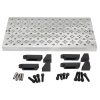 Tooling/Fixture Plate (12" x 6")
 Cut-Off Blade, P1N